This page also applies to the TM100 and TM120 ThinManager Ready platforms
Opening the case
The ML100 can be opened by the user. This does not void the warranty, however, any damage caused by doing so will not be covered.
- Ensure your body is discharged of any static electricity by touching a grounded metal surface.
- Remove the 4x phillips screws on the outside of the case.
- Use the tab for leverage to pull the bottom panel off

- The internals of the unit can now be accessed

VESA Mounting
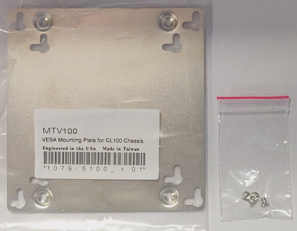
- Remove the mounting hardware from the packaging

- Using the included screws, attach the VESA plate to the bottom of the system.

- Grab the 4x VESA mounting screws from the accessory kit

- Locate the mounting holes on the rear of your monitor
- Install the mounting screws hand tight

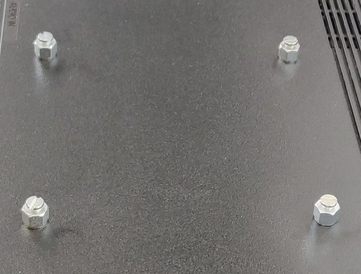
- Poke the VESA screw heads through the holes in the bottom of the mounting plate.
- Slide the system down and it will drop into place.
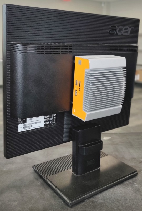
- Final installation shown.
ML100G-10 (TM100)
Jetway JNU93-2930 motherboard
Drivers
https://drive.google.com/drive/folders/1TX8v2Jq9i13gweJFjhYoUjteuEju0ZMM
Product Manual
https://drive.google.com/file/d/1OS3VDI8vUv9Vi4skQCSzaLflG6WyjXyv/view
Enable Auto Power On
Disconnect the system from all wire connections (power, ethernet, video, etc), then:
- Disconnect the unit from all wire connections (power, USB, ethernet, etc.)
- Locate the auto power on jumper
- The default position is disabled, unless specified otherwise at the time of purchase.
- Lift the jumper off and reinstall it so it connects both pins.
- Auto power on is now enabled.

Clear the CMOS
Disconnect the system from all wire connections (power, ethernet, video, etc), then:
● Locate the JBAT jumper pins near the ethernet port.
● Use a flathead screwdriver or other conductive object to short
the two pins together for 30 seconds.
● The CMOS is now clear.
● Power on the unit. Note: it may take 60 seconds to reconfigure
itself and restart. Wait patiently after turning it on.

ML100G-30
Intel NUC5i5MYBE motherboard
Drivers
https://drive.google.com/drive/folders/1UtB37qPK-VjirWWBksuq1Z8wVRiBqTH-
Product Manual
https://drive.google.com/file/d/1thaxo6Em2KMjEFdDtV8P_k-kNs_h3oYH/view
Enable Auto Power On
● Power on the unit and press the F2 key a few times to access the BIOS
● Click the Advanced button

● Click on the Power tab
● Locate the After Power Failure option and change it to Power on.
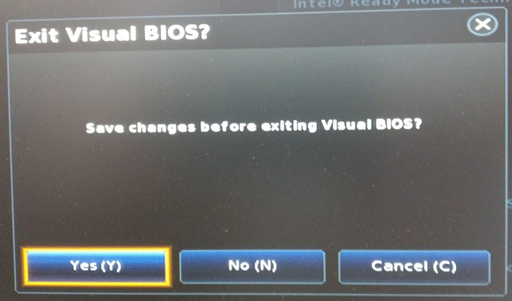
● Click the X
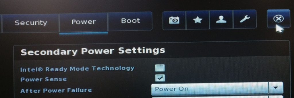
● Click Yes to save changes
● Auto power on is now enabled
Clear the CMOS
Disconnect the system from all wire connections (power, ethernet, video, etc), then:
Intel NUC boards do not have a traditional CMOS clear jumper.
Instead, they have a “recovery mode” jumper.
● Remove the yellow jumper
● With the jumper removed, power on the system
● It should display a recovery menu in ~30-60 seconds if
successful
● Power down and reinstall the jumper in the 1-2 position.
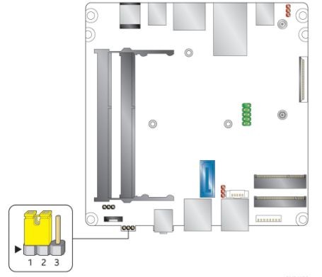
| Function | Jumper Setting | Action |
| Normal | 1-2 | Normal Operation |
| Lockdown | 2-3 | BIOS read-only |
| Recovery | None/Removed | Clear CMOS |
ML100G-31
Intel NUC7i3DNBE-P motherboard
Drivers
https://drive.google.com/drive/folders/1V9TQK-vowak_LRKWRhifT_uX3rbkRDQs
Product Manual
https://drive.google.com/file/d/1VoKaKsbx3FCPp7sAAkWWIU54syXSY8un/view
Enable Auto Power On
● Power on the unit and press the F2 key a few times to access the BIOS
● Click the Advanced button
● Click on the Power tab
● Locate the After Power Failure option and change it to Power on.
● Click the X

● Click Yes to save changes
● Auto power on is now enabled
Clear the CMOS
Disconnect the system from all wire connections (power, ethernet, video, etc), then:
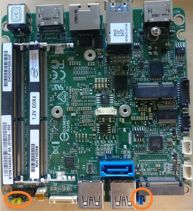
● Remove the blue jumper and install it onto both pins.
● Wait approximately 30 seconds
● Reinstall the jumper on a single pin
● The ME, MEBX, and AMT settings have been reset
● Remove the yellow jumper
● With the jumper removed, power on the system
● It should display a recovery menu in ~30-60
seconds if successful
● Power down and reinstall the jumper in the 1-2 position.
ML100G-40
ASRock 4X4-V1000M-P motherboard
Drivers
https://www.asrockind.com/overview.asp?Model=4X4%20BOX-R1000V#download
Product Manual
https://drive.google.com/file/d/1HtwLcemfHzn4K-cLNruFxBoaT_SoqnM9/view
Enable Auto Power On
https://drive.google.com/file/d/1HtwLcemfHzn4K-cLNruFxBoaT_SoqnM9/view
● Power on the unit and press F2 a few times to access the BIOS.
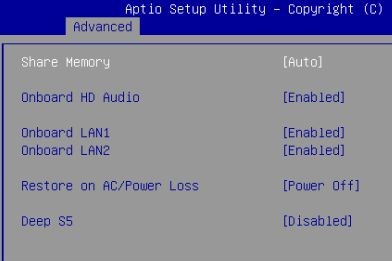
● Navigate to the Advanced tab
● Open the Chipset Configuration menu
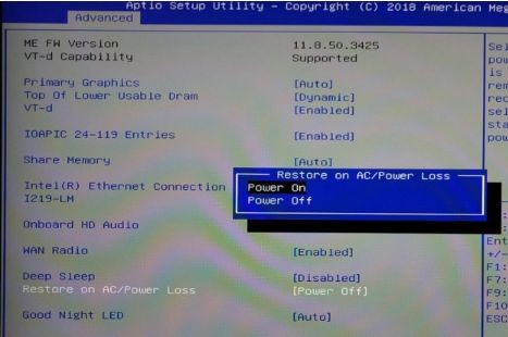
● Locate the Restore on AC/Power Loss option
● Set it to Power On
● Press escape twice to go back
● Navigate to the Exit tab, Save Changes and Exit
Clear the CMOS
Disconnect the system from all wire connections (power, ethernet, video, etc), then:
● Locate the clear CMOS jumper
● Move the jumper over by 1 pin
● Wait 30 seconds
● Restore the jumper to its original position
● Close up and power on the system. It may power cycle several times before it begins working again.

Troubleshooting
For increased reliability it is recommended to disable the Core Performance Boost BIOS setting. To disable the setting, navigate to:
Advanced -> CPU Configuration -> Core Performance Boost -> Set to “Disabled”
Press F10 to Save & Exit.
ML100G-41
ASRock 4×4-4300U / 4×4-4800U Motherboard -or-
ASRock 4×4-V2000V / 4×4-V2000M Motherboard
Drivers
https://www.asrockind.com/en-gb/4X4-4800U
https://www.asrockind.com/en-gb/4X4-V2000M
Product Manual
https://www.asrockind.com/en-gb/4X4-4800U
https://www.asrockind.com/en-gb/4X4-V2000M
Enable Auto Power On
The auto power on feature will automatically turn the ML100 back on after DC power is lost and restored. To enable it, a jumper needs to be moved inside the unit. The ML100 can be opened by the user. This does not void the warranty, however, any damage caused by doing so will not be covered.
- Ensure your body is discharged of any static electricity by touching a grounded metal surface.
- Remove the 4x phillips screws on the outside of the case.
- Use the tab for leverage to pull the bottom panel off

- Remove the two screws from the USB board and gently lift it out of the way, leaving it plugged in.

- Remove the blue jumper circled at the top and place it on the 2 pins circled in the bottom left.
- Note: We are borrowing the clear CMOS jumper for this procedure. If CMOS needs to be cleared at a later date, keep that in mind.
- Auto power on is now enabled and good to go.
Troubleshooting
For increased reliability on systems with the optional 4X4-V2000M CPU, it is recommended to disable the Core Performance Boost BIOS setting. To disable the setting, navigate to:
Advanced -> CPU Configuration -> Core Performance Boost -> Set to “Disabled”
Press F10 to Save & Exit.
Clearing the CMOS
- Disconnect the unit from all wire connections (power, USB, ethernet, etc.)
- Remove the 4x phillips screws on the outside of the case.
- Use the tab for leverage to pull the bottom panel off
- Remove the two screws from the USB board and gently lift it out of the way, leaving it plugged in.

- Locate the clear CMOS jumper
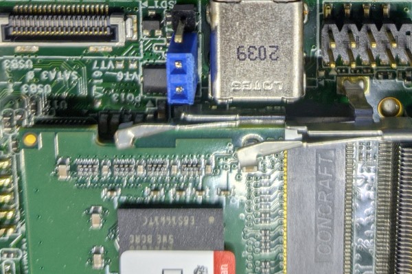
- The jumper will initially be in this position.
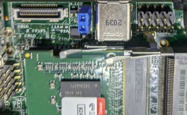
- Move the jumper over by 1 pin

- Wait 30 seconds
- Move the jumper back to its original position.
- Re-assemble and power up the PC. Do not touch it for 2 minutes to allow it time to reconfigure itself. If it still does not respond, contact OnLogic support.
ML100G-50
ASRock NUC-6300U-P motherboard
Drivers
https://drive.google.com/drive/folders/1VMfUxIn9okY0mfn-IgQ5oVNncW3aextu
Product Manual
https://drive.google.com/file/d/13yHe0PTb5fp3aTweuh_qqMyzETCBQ1Ww/view
Enable Auto Power On
- Power on the unit and press F2 a few times to access the BIOS.
- Navigate to the Advanced tab
- Open the Chipset menu
- Locate the Restore on AC/Power Loss option
- Set it to “Power On”
- Press escape twice to go back
- Navigate to the Exit tab, Save Changes and Exit
Clearing the CMOS
Disconnect the system from all wire connections (power, ethernet, video, etc), then:
- Locate the clear CMOS pad (circled below)
- Use a flathead screwdriver or other piece of metal to short the two halves together for 30 seconds
- Reinstall the bottom plate and power the unit on.
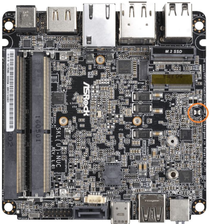
ML100G-51 & ML100G-52
ASRock NUC-8265U, NUC-8365UE-IPC, or NUC-8665UE-IPC motherboard
Drivers
https://drive.google.com/drive/folders/1ETScPd206S9mKL-OtbB9q0H2-T6mB4FF
Product Manual
https://drive.google.com/file/d/1Uc_DGjvakIeSkq3awYb5HfhqHvPpLayW/view
Enable Auto Power On
● Locate the PWR_JP1 jumper
● Move it over by 1 pin
● Auto power on is now enabled

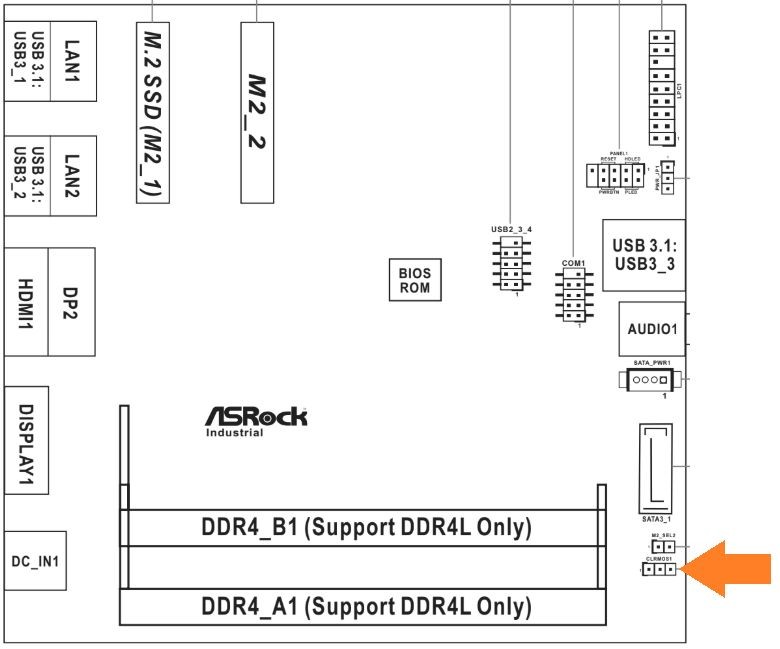
Clear the CMOS
Note: This procedure requires opening the case first. Instructions for opening the case can be found here.
- Disconnect the unit from all wire connections (power, USB, ethernet, etc.)
- Locate the CLRMOS1 jumper
- Move the jumper over by 1 pin
- Wait 30 seconds
- Restore the jumper to its original position
- Close up and power on the system. It may power cycle several times before it begins working again.
ML100G-53 (TM120)
ASRock NUC-6305E, NUC-1115G4, NUC-1135G7, NUC-1145G7E-P, or NUC-1165G7 motherboard – depending on processor selection
Drivers
https://www.asrockind.com/en-gb/NUC-1115G4
Click “Support” on the blue bar
Product Manual
https://download.asrock.com/IPC/Manual/NUC–1115G4.pdf
Enable Auto Power On

- Locate the jumper from your system’s accessory box.
- If you need a replacement, this is a standard 2.54mm jumper. Available from DigiKey.
- Ensure your body is discharged of any static electricity by touching a grounded metal surface.
- Disconnect the unit from all wire connections (power, USB, ethernet, etc.)
- Remove the 4x phillips screws on the outside of the case.
- Use the tab for leverage to pull the bottom panel off

- Locate the auto power on header

- Place the jumper onto the header. Use needle nose pliers if available.

- Auto power on is now enabled.
- Re-assemble the system and it will turn on automatically when you plug it in.
Clearing the CMOS
- Disconnect the unit from all wire connections (power, USB, ethernet, etc.)
- Remove the 4x Philips screws on the outside of the case.
- Use the tab for leverage to pull the bottom panel off

● Locate the clear CMOS jumper

- Using a flathead screwdriver or similar conductive metal object, short the outer 2 pins of the CMOS header for 30 seconds.
- Re-assemble and power up the system. Wait patiently for 2 minutes as it will need to restart a couple times to reconfigure.
- If the unit is still unresponsive after 2 minutes, contact support@onlogic.com.