The TM line from OnLogic comes pre-configured with a custom BIOS that boots directly to the Rockwell Automation’s ThinManager boot ROM. OnLogic is responsible for any hardware issues, while the Rockwell team can help with anything pertaining to the software, configuration, or setup.

For help with software or configuration issues, click here for Rockwell support.
Note on ThinManager Version 11
With the release of ThinManager Version 11, Rockwell Automation’s ThinManager software no longer boots from Legacy Boot Mode in the system BIOS. ThinManager now boots using UEFI Mode. In addition, Intel does not support Legacy Boot Mode on newer generation processors.
As a result, only the following OnLogic products support versions of ThinManager older than Version 11:
| TM200 | TM300 |
| TM400 | TM700 |
It is highly recommended by both Rockwell Automation and OnLogic that customers use the most up to date stable release of ThinManager.
Product Line Update (May, 2023)
Software updates frequently bring valuable new features and enhanced security to users, but they can also bring headaches to IT and OT teams who need to implement the changes. As a result, organizations may remain on a legacy version of a given software package for extended periods. However, inevitably, there ultimately comes a time when it no longer makes sense for organizations to support legacy versions of software.
ThinManager Software Updates
With the release of ThinManager version 11 in 2018, ThinManager switched to utilizing UEFI boot mode instead of a Preboot eXecution Environment (PXE). Users on legacy versions of ThinManager require hardware that supports PXE. However, only systems with Intel 4th generation Intel Atom processors (Bay Trail) and older support that feature and thus support ThinManager v10 or older.
These older platforms are reaching the end of their lifecycle and, as such, we are discontinuing them. We are here to help you understand what that means for your deployments and the benefits of migrating to a newer version of ThinManager.

ThinManager Update FAQ
- What are the benefits of upgrading to newer versions of ThinManager?
- Along with new features such as event-based delivery, REST API configuration, and container virtualization, the most important feature of the latest versions of ThinManager is DCOM Hardening patches to help protect your system against intrusions.
- The biggest issue with legacy software is that without security patches, your system is left vulnerable to known exploits. ThinManagers version 10 and older no longer receive security patches making migration a priority.
- ThinManager offers some additional resources:
- To learn more about the life cycle status of ThinManager versions and what it means to be supported, see the Version Life Cycle Policy
- To learn more about specific features with each released version of ThinManager, see the ThinManager History page
- To learn about new features of 12.1 and 13.0, see the “New Features” product profile page
- What should I upgrade first, my hardware or my ThinManager software?
- You will need to upgrade your ThinManger Server first. OnLogic ThinManager Ready Clients that use legacy PXE boot are compatible with the latest versions of ThinManager. You will then have the ability to use newer OnLogic ThinManager Ready Clients that use UEFI boot.
- I have OnLogic hardware that I used with earlier versions of ThinManager. Will it still work with newer versions of ThinManager?
- If you are using a system from OnLogic such as the TM700 with a legacy ThinManager version between v6-v10, it will still work with the newest versions of ThinManager.
- If you are using a firmware version older than v6, you should contact ThinManager for support.
- I am unable to upgrade my ThinManager software. When is OnLogic discontinuing systems that support my legacy software?
As always, our team is available to answer any questions that you might have about our ThinManager-ready thin clients.
Hardware Troubleshooting
The following sections give an overview of common hardware troubleshooting steps for each TM system.
TM100 (ML100G-10)
Jetway JNU93-2930 motherboard
Motherboard Manual
https://drive.google.com/file/d/1OS3VDI8vUv9Vi4skQCSzaLflG6WyjXyv/view
How to clear the CMOS
If your unit fails to boot or power on, a CMOS reset may help. You will need to open the unit to perform the reset. This does not void your warranty, however, any damage caused by doing so will not be covered. Ensure your body is discharged of any static electricity by touching a grounded metal surface.
- Remove the 4x phillips screws on the outside of the case.
- Use the tab for leverage to pull the bottom panel off

● Locate the JBAT jumper pins near the ethernet port.
● Use a flathead screwdriver or other conductive object to short
the two pins together for 30 seconds.
● The CMOS is now clear.
● Power on the unit. Note: it may take 60 seconds to reconfigure
itself and restart. Wait patiently after turning it on.

TM120 (ML100G-53)
Thinmanager Firmware Version 13.0.1-9.3 is required to support the new I225 LAN Interface.
BIOS
| BIOS | Release Date |
| 1.40M (Current version) | 06/03/2022 |
| Previous: No previous versions | — |
Opening the case
The TM120 can be opened by the user. This does not void the warranty, however, any damage caused by doing so will not be covered.
- Ensure your body is discharged of any static electricity by touching a grounded metal surface.
- Remove the 4x phillips screws on the outside of the case.
- Use the tab for leverage to pull the bottom panel off
- The internals of the unit can now be accessed

ASRock NUC-6305E, NUC-1115G4, NUC-1135G7, or NUC-1165G7 motherboard – depending on processor selection
Drivers
https://www.asrockind.com/en-gb/NUC-1115G4
Click “Support” on the blue bar
Product Manual
https://download.asrock.com/IPC/Manual/NUC–1115G4.pdf
Enable Auto Power On

- Locate the jumper from your system’s accessory box.
- If you need a replacement, this is a standard 2.54mm jumper. Available from DigiKey.
- Ensure your body is discharged of any static electricity by touching a grounded metal surface.
- Remove the 4x phillips screws on the outside of the case.
- Use the tab for leverage to pull the bottom panel off

- Locate the auto power on header

- Place the jumper onto the header. Use needle nose pliers if available.

- Auto power on is now enabled.
- Re-assemble the system and it will turn on automatically when you plug it in.
Clearing the CMOS
- Remove the 4x phillips screws on the outside of the case.
- Use the tab for leverage to pull the bottom panel off

● Locate the clear CMOS jumper

- Using a flathead screwdriver or similar conductive metal object, short the outer 2 pins of the CMOS header for 30 seconds.
- Re-assemble and power up the system. Wait patiently for 2 minutes as it will need to restart a couple times to reconfigure.
- If the unit is still unresponsive after 2 minutes, contact support@onlogic.com.
TM200 (ML210G-10)
Drivers
https://drive.google.com/open?id=1WBrh4LQuMyYY_Tr93q21alaeRNu6rNt0
How to clear the CMOS
If your unit fails to boot or power on, a CMOS reset may help. You will need to open the unit to perform the reset. This does not void your warranty, however, any damage caused by doing so will not be covered. Ensure your body is discharged of any static electricity by touching a grounded metal surface.
- Ensure your body is discharged of any static electricity by touching a grounded metal surface.
- Remove the 6x phillips screws on the outside of the case.
- If your unit has COM ports, remove the standoffs for those as well.
- The backplate will then be loose and can be removed.
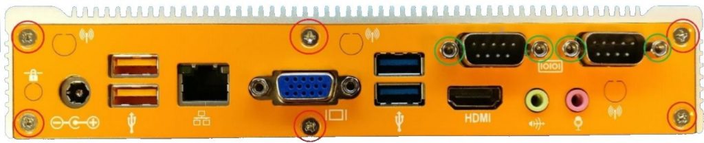
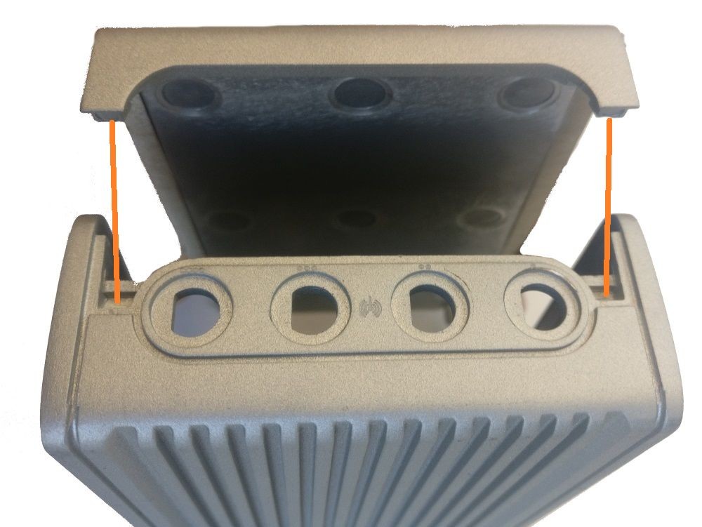
- Note the ridge between the lid and the heat block on the processor
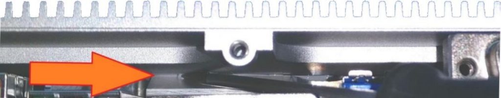
- Insert a flathead screwdriver into the ridge and pry them apart using a twisting motion.
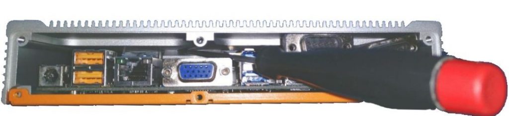
- Tilt the lid to a 45 degree angle and pull it loose from the rest of the case.
- You now have full access to the internals
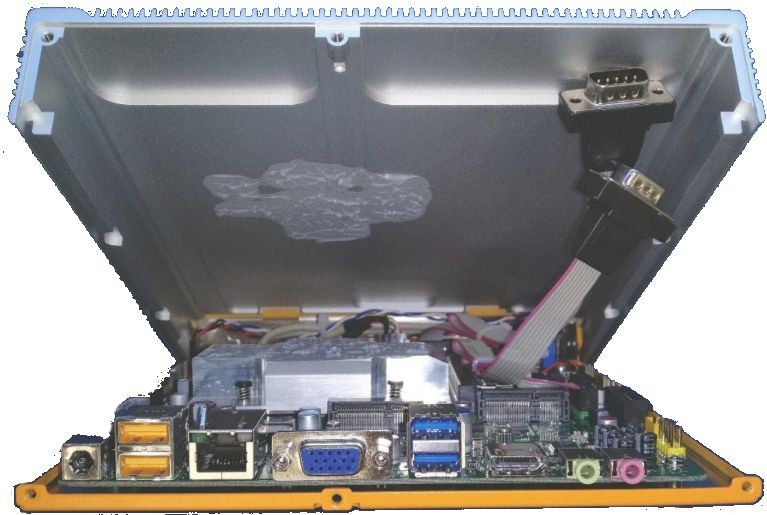
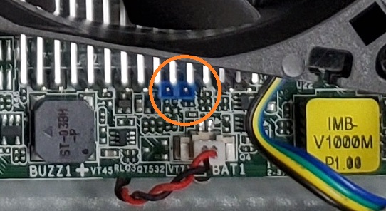
● Locate the clear CMOS jumper next to the purple header
● Move the jumper over by 1 pin
● Wait 30 seconds
● Restore the jumper to the original position
● The CMOS is now clear. Reassemble the unit and power on.
● It may reboot several times to reconfigure itself.
TM250 (ML350G-10)
How to clear the CMOS
If your unit fails to boot or power on, a CMOS reset may help. You will need to open the unit to perform the reset. This does not void your warranty, however, any damage caused by doing so will not be covered. Ensure your body is discharged of any static electricity by touching a grounded metal surface.
- Ensure your body is discharged of any static electricity by touching a grounded metal surface.
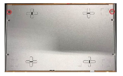
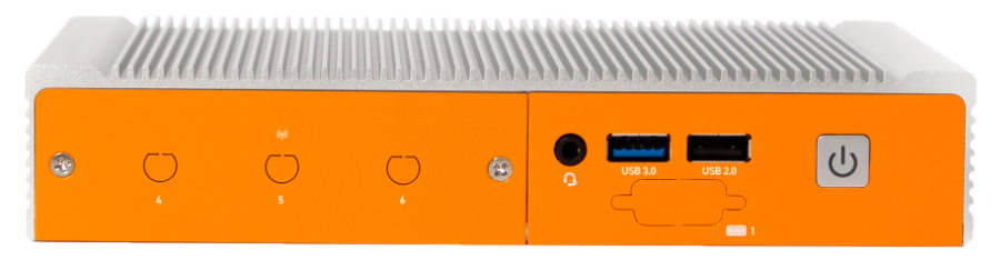
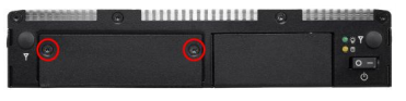
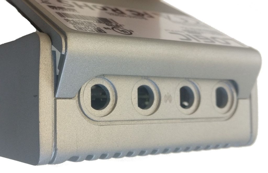
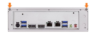
- Remove the two silver Phillips screws from the bottom of the unit as circled in red below:
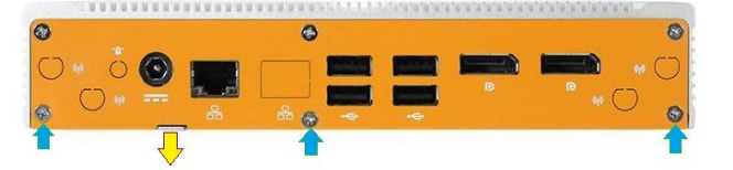
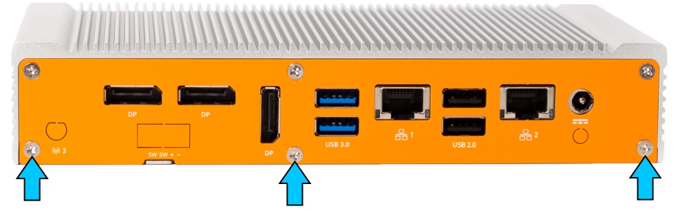
- Remove the bottom 3 Phillips screws from the back plate (blue arrows shown below).
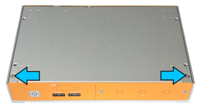
- Using your fingernail or a Flathead screwdriver, pry the bottom plate off using the provided leverage tab (yellow arrow shown below).
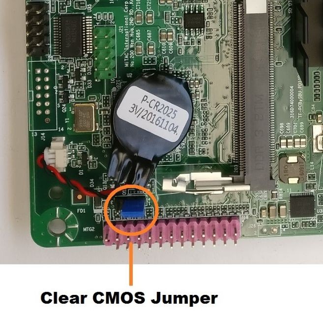
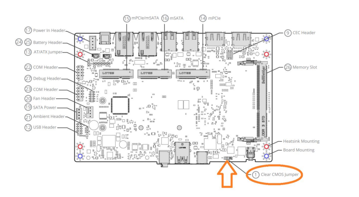
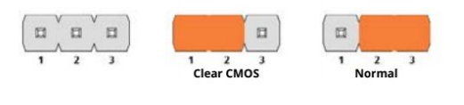
- Locate the Clear CMOS jumper as shown below:
- Remove the jumper from pins 2 and 3.
- Install it onto pins 1 and 2, moving it over by 1 pin.
- Wait 30 seconds.
- Restore the jumper to its original 2-3 position. The CMOS is now clear.
- Re-install the bottom plate and all 5 screws.
Note: The unit may power cycle several times before it boots up. This is normal.
TM260 (HX330)
Drivers and Manuals
Spec Sheets & Dimensional Drawings:
HX310 / HX330 / TM260
TM260 ThinManager Firmware
The TM260 (the HX330 with ThinManager Ready firmware) is compatible with ThinManager 11 or higher, with Firmware page 9. Customers interested in the ThinManager WiFi Boot option should use ThinManager 13.2 to enable this feature. Checkout our OnLogic Blog with more info about ThinManager WiFi Boot.
Disassembly Guide
Opening the system does not void the warranty, however, some precautions are necessary to avoid damaging the unit. Any damaged caused will not be covered by warranty.
- Perform this disassembly in an area free of static discharge
- Before beginning, touch a grounded metal surface to discharge your body of static electricity
- Remove the bottom 3 Phillips P2 screws from the back of the system
- Remove the two screws from the bottom of the case
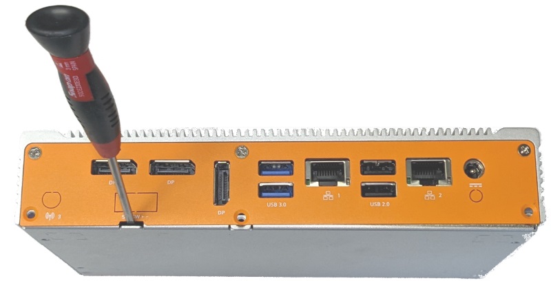
- Pry the bottom lid off using a flathead screwdriver
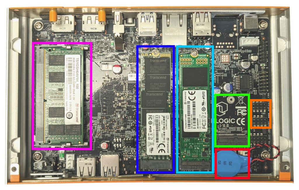
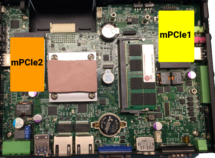
- The internals of the system are now accessible, including the RAM, Primary SSD, Secondary SSD, WiFi card, Serial/COM headers, and CMOS battery.
Enabling Auto Power On
The system can be configured to turn on automatically when DC power is connected. This is useful for power outage recovery or if the unit is mounted in a hard to reach location. You can enable Auto Power On by following the steps listed below.
- Follow the Disassembly Guide directly above
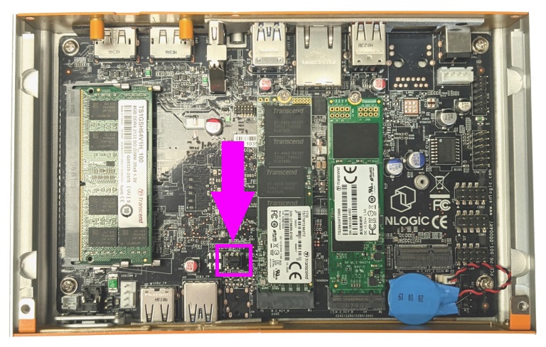
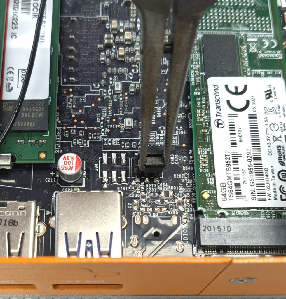
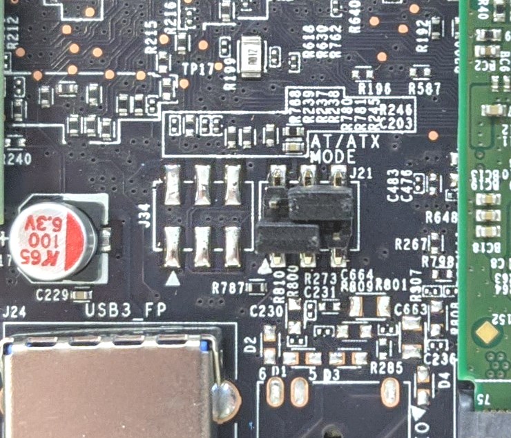
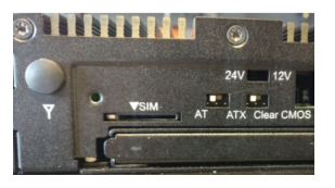
- Locate the jumper blown shown here in purple
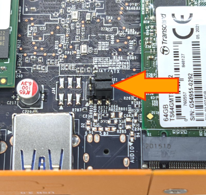
- The bottom jumper in this image (closest to the outside of the system) controls auto power on. It is called the AT/ATX jumper.
- Use needlenose pliers or your fingernails to grab the jumper and remove it from the pins.
- Reinstall the jumper as shown.
- Auto power on is now enabled (AT Mode)
Troubleshooting
Clearing the CMOS
If your unit fails to boot or power on, a CMOS reset may help. You will need to open the unit to perform the reset. This does not void your warranty, however, any damage caused by doing so will not be covered. Ensure your body is discharged of any static electricity by touching a grounded metal surface.
- Follow the Disassembly Guide above
- Locate the jumper shown here in purple
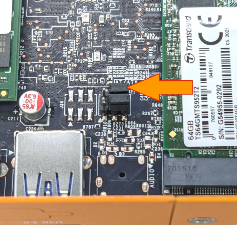
- The top jumper shown here will clear the CMOS.
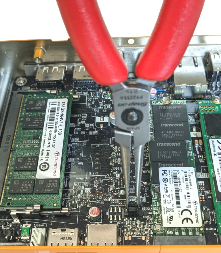
- Use needlenose pliers or your fingernails to grab the jumper and remove it from the pins.
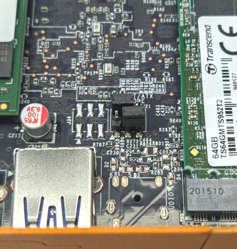
- Reinstall the jumper as shown.
- Leave the jumper in place for 30 seconds.
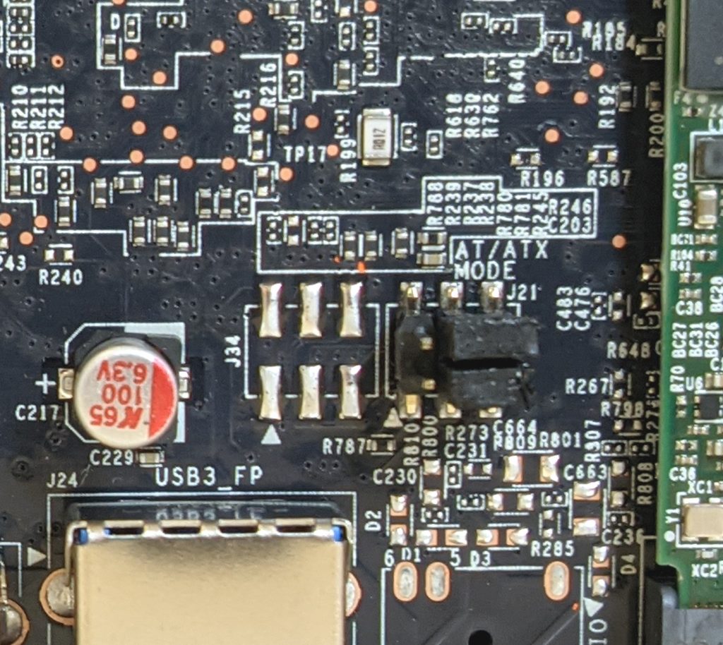
- Restore the jumper to its original position
TM300 (DC-1100-P)
DC-1100 Motherboard Manual
https://www.cincoze.com/data/files/201811/Manual_DC-1100_V1.40_2016083001.pdf
How to clear the CMOS
If your unit fails to boot or power on, a CMOS reset may help. You will need to open the unit to perform the reset. This does not void your warranty, however, any damage caused by doing so will not be covered. Ensure your body is discharged of any static electricity by touching a grounded metal surface.
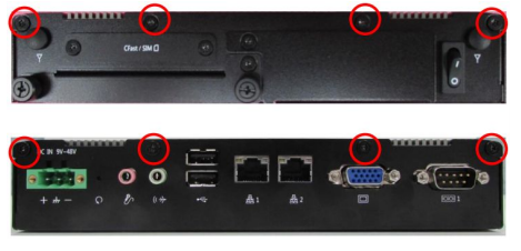
- Remove the 4x Torx T9 screws from the bottom plate.
- The plate is now loose and can be lifted off.
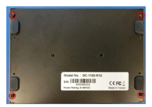
The storage and RAM are now accessible.
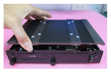
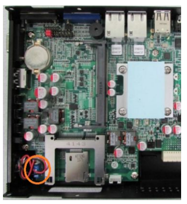
- To continue with the CMOS reset, remove the 3 circled phillips screws.
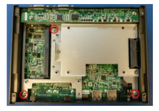
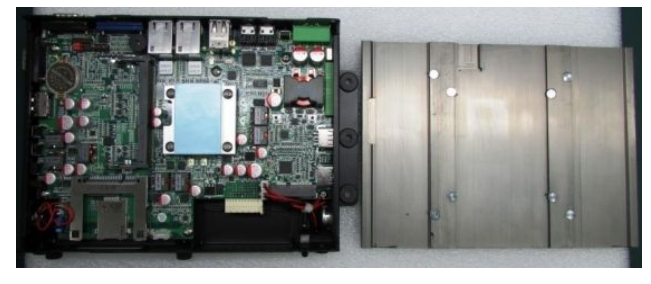
- The lid can now be pulled apart from the rest of the system. This may take a moderate amount of force but can be done using only your hands. It can be helpful to grab the COM ports for leverage.
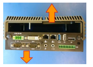
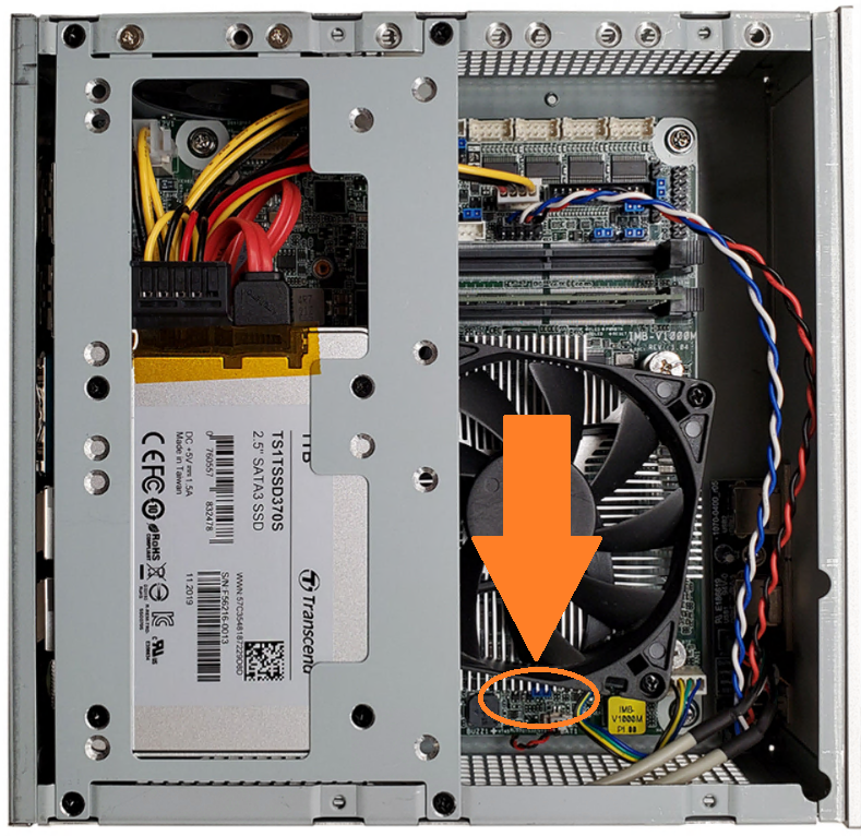
- With the lid separated, you can now access the CMOS reset switch and battery.
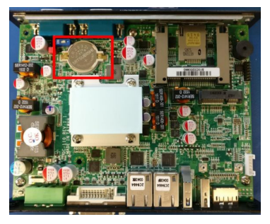
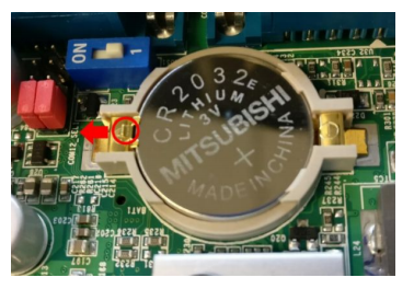
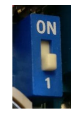
- Flip the blue switch to the ON position for 30 seconds and then return it to the 1 position. The CMOS is now clear.
- If you would like to replace the CMOS battery, you may do so now. Slide the gold tab to release the battery.
- Reassemble the unit and test it again. If you continue to have issues, contact technical support.
Note: if you unit has WiFi, be cautious of the WiFi pigtail routing during re-assembly. Ensure the cables are away from the screw holes so they do not get damaged by the screws.
TM400 (P1001)
How to clear the CMOS
If your unit fails to boot or power on, a CMOS reset may help. You will need to open the unit to perform the reset. This does not void your warranty, however, any damage caused by doing so will not be covered. Ensure your body is discharged of any static electricity by touching a grounded metal surface.
Required tools: T10 Torx Driver
- Remove the 8x torx screws that hold the lid in place
- Lift the lid off vertically. Moderate force may be required to break the thermal seal.
- Set the lid aside
- The CMOS battery and CMOS reset switch are now exposed. The CMOS can be cleared by moving the blue switch to the ON position for 30 seconds
- The CMOS has now been cleared
- Reinstall the top cover and the torx screws
NOTE: The unit may power cycle several times before it boots up. This is normal.
TM410 (P1101)
Manuals
How to Clear CMOS on TM410/P1101
Required tools: T10 Torx driver
- Remove the two Torx T10 screws
- Slide the Clear CMOS switch to the other position
- Wait 30 seconds
- Return the switch to its original position
- The CMOS is now clear
NOTE: The unit may power cycle several times before it boots up. This is normal.
Disassembly
The P1101 can be opened by the user. This does not void the warranty, however, any damage caused by doing so will not be covered. Some precautions should be taken to avoid damaging the unit:
- Perform this disassembly in an area free of static discharge
- Before beginning, touch a grounded metal surface to discharge your body of static electricity
Remove x8 screws from the back/top of the system as indicated. You will need a Torx T10 screwdriver.
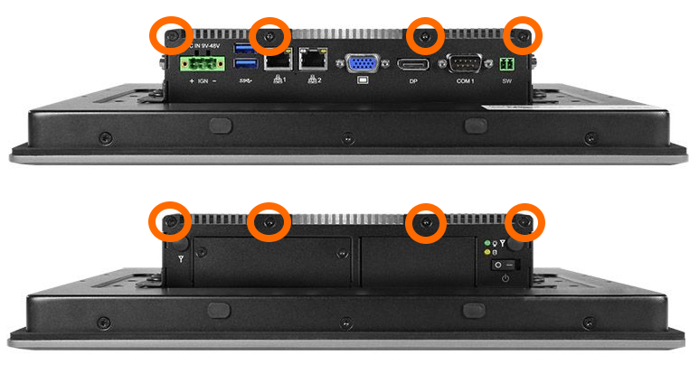
Remove the heatsink lid to gain access to the motherboard.
TM610 (MC610-50)
BIOS
| BIOS | Release Date |
| 1.40B (Current version) | 01/21/2019 |
| Previous: No previous versions | — |
Motherboard Manual
https://download.asrock.com/Manual/IMB-1212.pdf
Using multiple displays
By default, only the Mini DP ports in the expansion bay are enabled. The motherboard’s onboard HDMI and VGA ports can be enabled in the BIOS to support additional displays.
Press the Del and F2 keys at startup to access the BIOS.

Navigate to Advanced > Chipset Configuration. Set the following options:

Primary Graphics Adapter   [Onboard]
IGPU Multi-Monitor   [Enabled]
Active LVDS  [Disabled]

Press F10 to Save & Exit.
The onboard HDMI/VGA are now used as the primary display ports and all ports are enabled.
How to clear the CMOS
If your unit fails to boot or power on, a CMOS reset may help. You will need to open the unit to perform the reset. This does not void your warranty, however, any damage caused by doing so will not be covered. Ensure your body is discharged of any static electricity by touching a grounded metal surface.
The case is very simple to open. To do so, remove the two screws from the back and slide the lid off towards the rear.

- Locate the clear CMOS jumper
- Move the jumper over by 1 pin
- Wait 30 seconds
- Restore the jumper to its original position
- The CMOS is now clear

TM700 (CL100)
Troubleshooting the CL100
If your unit fails to boot or power on, a CMOS reset may help. You will need to open the unit to perform the reset. This does not void your warranty, however, any damage caused by doing so will not be covered. Ensure your body is discharged of any static electricity by touching a grounded metal surface.
- Perform this disassembly in an area free of static discharge
- Before beginning, touch a grounded metal surface to discharge your body of static electricity

Opening the CL100 case
- Unplug the system and turn it upside down
- If applied, remove the rubber feet to access the screws
- Next, use a small P1 Phillips driver to remove the screws
- Now the bottom plate can now be removed. There may be slight resistance from the sticky thermal pad found inside

Clearing the CL100 CMOS
- First, locate the clear CMOS pad (circled in red)
- Then use a flathead screwdriver or other piece of metal to short the two halves together for 30 seconds
- After that, reinstall the bottom plate and power on the CL100. If it fails to function at this point, you may need to send it in for repair

TM710 / TM110 (CL250G-P / CM230G-P)
System Manual
http://static.onlogic.com/resources/manuals/OnLogic-CL200-Series-Manual-v1.pdf
How to clear the CMOS
If your unit fails to boot or power on, a CMOS reset may help. You will need to open the unit to perform the reset. This does not void your warranty, however, any damage caused by doing so will not be covered. Ensure your body is discharged of any static electricity by touching a grounded metal surface.
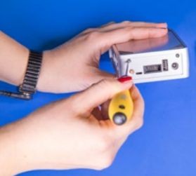
- Remove the two silver Phillips screws
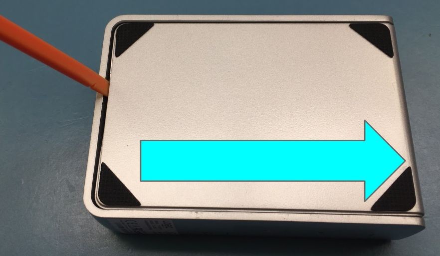
- Use a flathead screwdriver or similar tool to gently lever the bottom cover off
- Locate the Clear CMOS jumpers
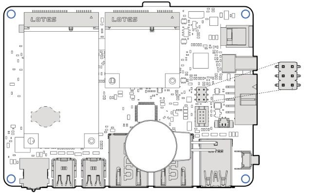
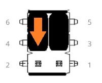
- Remove the black jumper from pins 6 and 4
- Install it onto pins 4 and 2, moving it down by 1 pin
- Wait 30 seconds
- Restore the jumper to its original 6-4 position
- The CMOS is now clear
- Hinge the bottom plate back onto the system by aligning the tabs
- Reinstall the silver Phillips screws
TM800 (MC510-40)
How to clear the CMOS
If your unit fails to boot or power on, a CMOS reset may help. You will need to open the unit to perform the reset. This does not void your warranty, however, any damage caused by doing so will not be covered. Ensure your body is discharged of any static electricity by touching a grounded metal surface.
The case is very simple to open. To do so, remove the two screws from the back and slide the lid off towards the rear.
- Locate the clear CMOS jumper
- Move the jumper over by 1 pin
- Wait 30 seconds
- Restore the jumper to its original position
- The CMOS is now clear