This article also applies to the TM250.
Documents and Downloads
ML350G-10 Spec Sheet & Dimensional Drawings
Drivers
BIOS Updates
| Bios Version | Link |
|---|---|
| A09 | Download |
Auto Power On
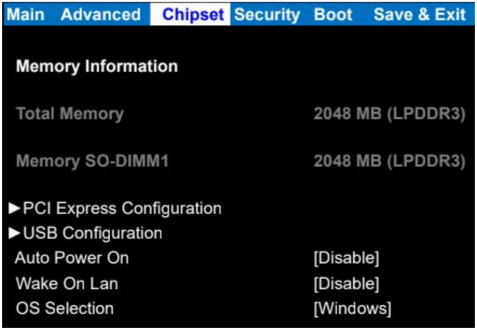
- Power on the ML350 and press the Esc key a few times to access the BIOS
- Navigate to the Chipset tab
- Change auto power on to [enable]
- Save & Exit
- The ML350 will now automatically turn on when power is connected
Opening the ML350
The ML350 can be opened by the user. This does not void the warranty, however, any damage caused by doing so will not be covered. Here are the steps to opening your ML350:
- Ensure your body is discharged of any static electricity by touching a grounded metal surface.
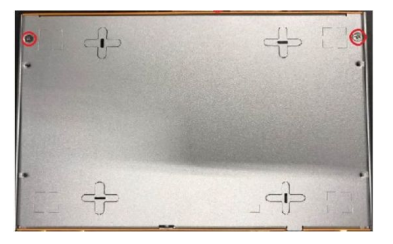
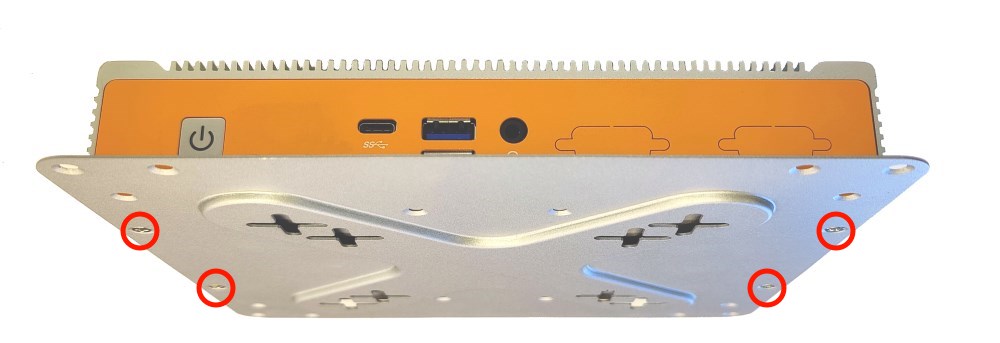
- Remove the two silver Phillips screws from the bottom of the unit as circled in red below:
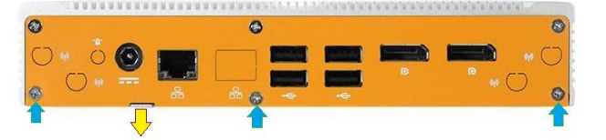
- Remove the bottom 3 Phillips screws from the back plate (blue arrows shown below).
- Using your fingernail or a Flathead screwdriver, pry the bottom plate off using the provided leverage tab (yellow arrow shown below).
How to Clear the CMOS
- Locate the Clear CMOS jumper as shown below:
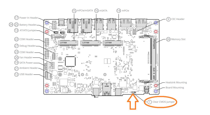
- Remove the jumper from pins 2 and 3.
- Install it onto pins 1 and 2, moving it over by 1 pin.
- Wait 30 seconds.
- Restore the jumper to its original 2-3 position. The CMOS is now clear.

- Re-install the bottom plate and all 5 screws.
Note: The unit may power cycle several times before it boots up. This is normal.
Installing COM Ports
VESA Mounting
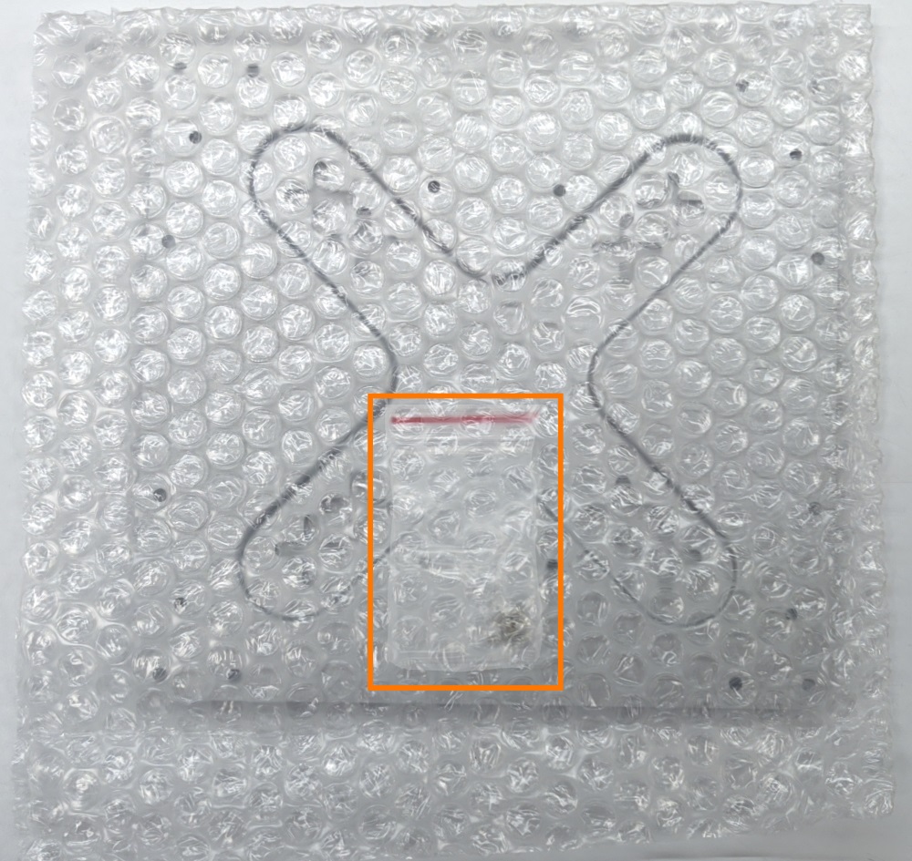
- Unpack the VESA mounting plate and remove the bubble wrap.
- Be sure not to throw away the screw bag inside.
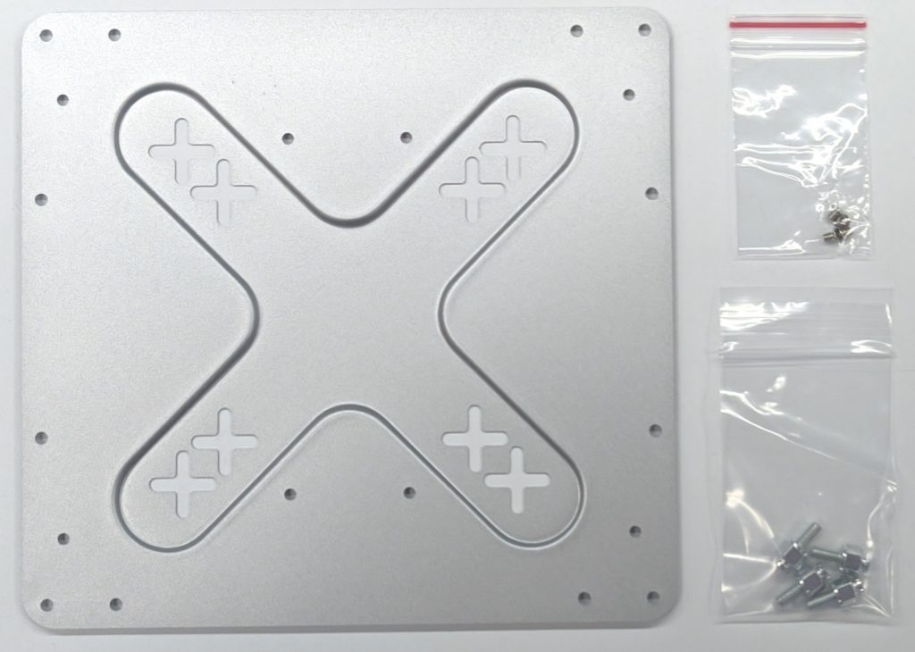
- You should have everything pictured here.
- Use the smaller of the included screws to attach the mounting plate to the bottom of your system.
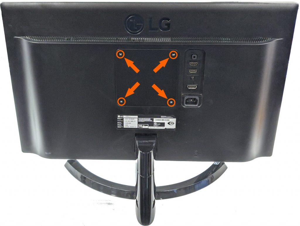
- Locate the VESA screw holes on the back of your monitor or mounting arm.
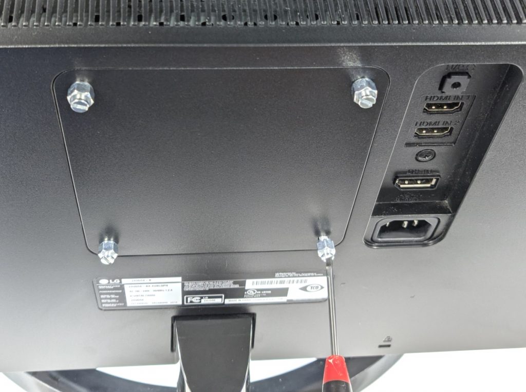
- Install the 4 bolts hand tight.
- Hang the system on the back of the display by lining up the bolts with the holes.
- Push the bolt head through the center of the + cutouts and slide the system down to lock in place.
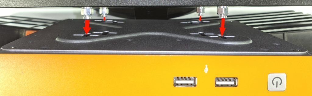
- Mounting plate shown without PC for illustration purposes
- Make sure the PC slides downward and all 4 bolts are engaged.