This also applies to the TM260 platform.
Drivers and Manuals
Spec Sheets & Dimensional Drawings:
HX310 / HX330 / TM260
Drivers (Windows 10) (Follow these steps for help installing via Device Manager)
Hardware Control Application (HWC)
| Version | Release Date | Link | Release Notes |
|---|---|---|---|
| v1.2.1 | 10/11/2023 | Download HWC Program must run as administrator in CMD | Fixes issue with Version-Check warning. * Note that the CAN baudrate is fixed at 1M. Please see our C-Based PSE-Examples for setting the baudrate programmatically. |
Linux Support
This model uses the new Intel GPY115/EC1000S Ethernet controller provided by the Elkhart Lake platform. Some operating systems are not compatible, or require additional setup by the user for this Ethernet controller.
*For systems purchased before March 1st 2023, Ubuntu can be installed after the Ethernet firmware has been updated. Customers interested in this can contact OnLogic Tech Support to RMA the system for this update.
Frequently Asked Questions (FAQ)
Refer to page 29-32 in the system manual for mounting diagrams
The system draws approximately 26 watts at full load. We recommend a 36 watt or higher power supply.
Download the drivers using the link above and then follow this guide to install them.
The operating voltage is 5-48v with isolation. The amperage limit is 150mA.
TM260 ThinManager Firmware
The TM260 (the HX330 with ThinManager Ready firmware) is compatible with ThinManager 11 or higher, with Firmware page 9. Customers interested in the ThinManager WiFi Boot option should use ThinManager 13.2 to enable this feature. Checkout our OnLogic Blog with more info about ThinManager WiFi Boot.
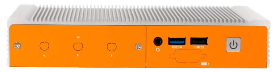
Disassembly Guide
Opening the system does not void the warranty, however, some precautions are necessary to avoid damaging the unit. Any damaged caused will not be covered by warranty.
- Perform this disassembly in an area free of static discharge
- Before beginning, touch a grounded metal surface to discharge your body of static electricity
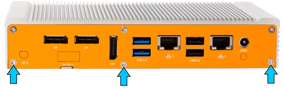
- Remove the bottom 3 Phillips P2 screws from the back of the system
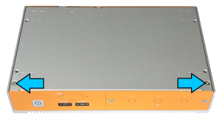
- Remove the two screws from the bottom of the case
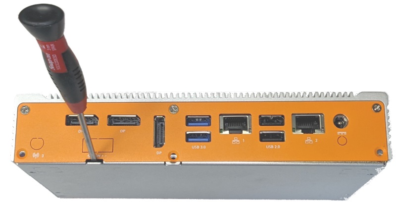
- Pry the bottom lid off using a flathead screwdriver
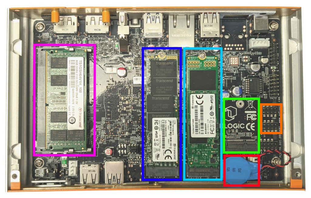
- The internals of the system are now accessible, including the RAM, Primary SSD, Secondary SSD, WiFi card, Serial/COM headers, and CMOS battery.
Enabling Auto Power On
The system can be configured to turn on automatically when DC power is connected. This is useful for power outage recovery or if the unit is mounted in a hard to reach location. You can enable Auto Power On by following the steps listed below.
- Follow the Disassembly Guide directly above
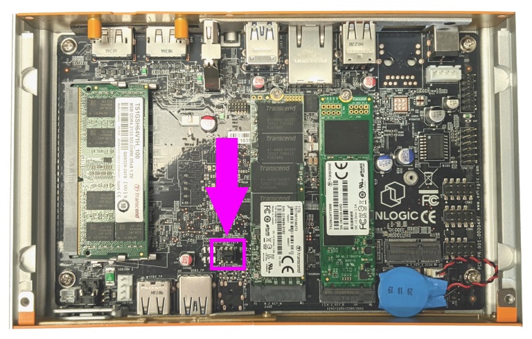
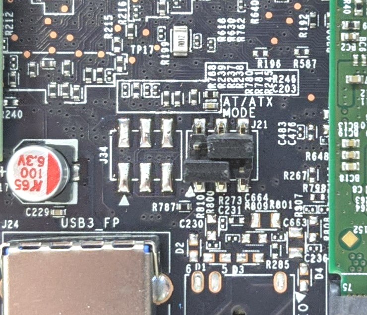
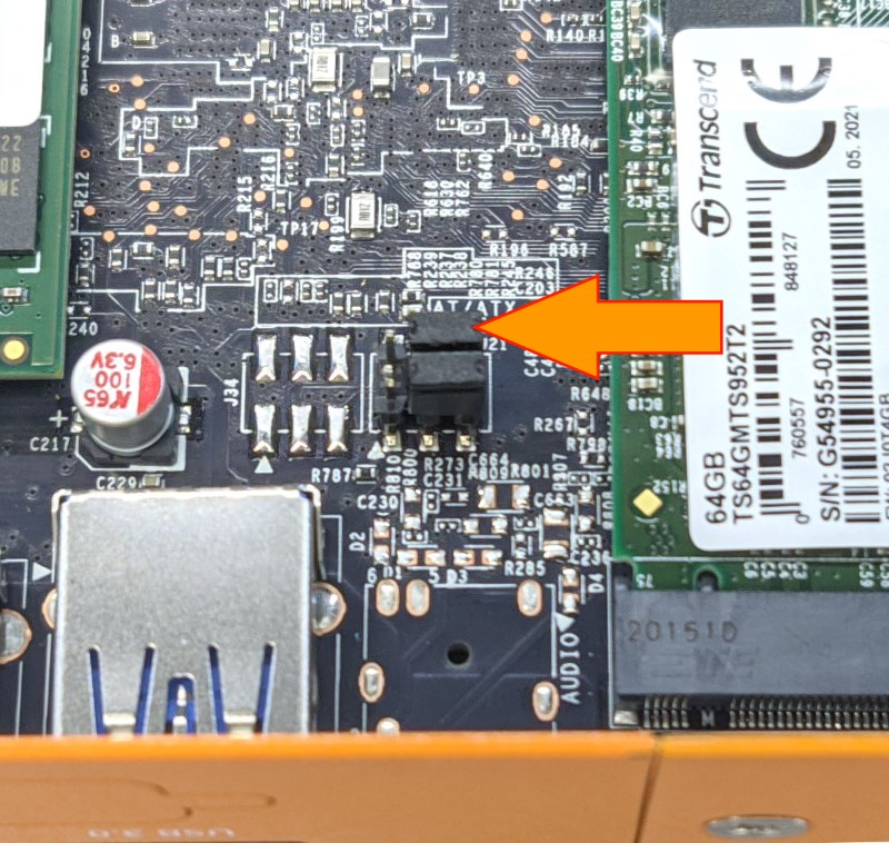
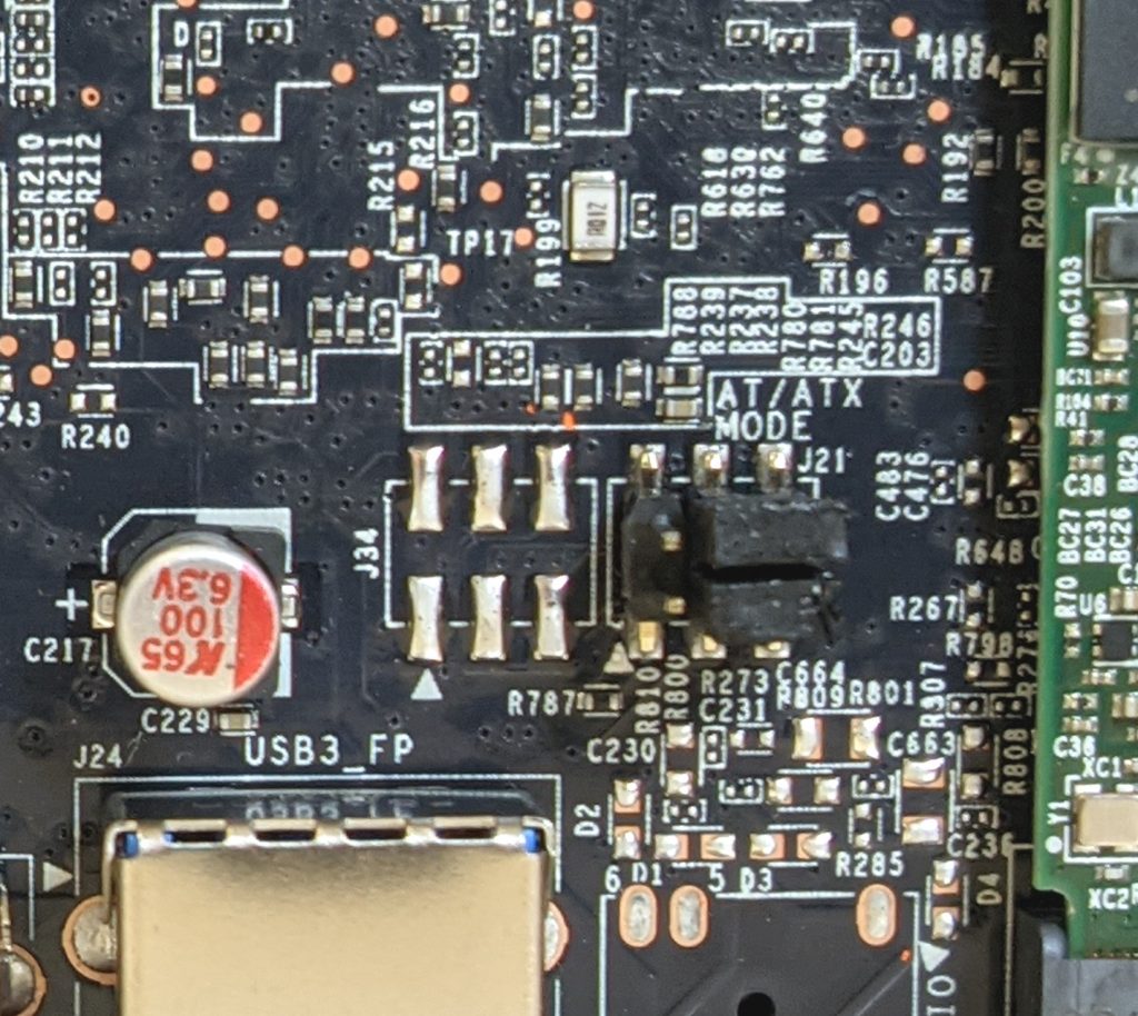
- Locate the jumper blown shown here in purple
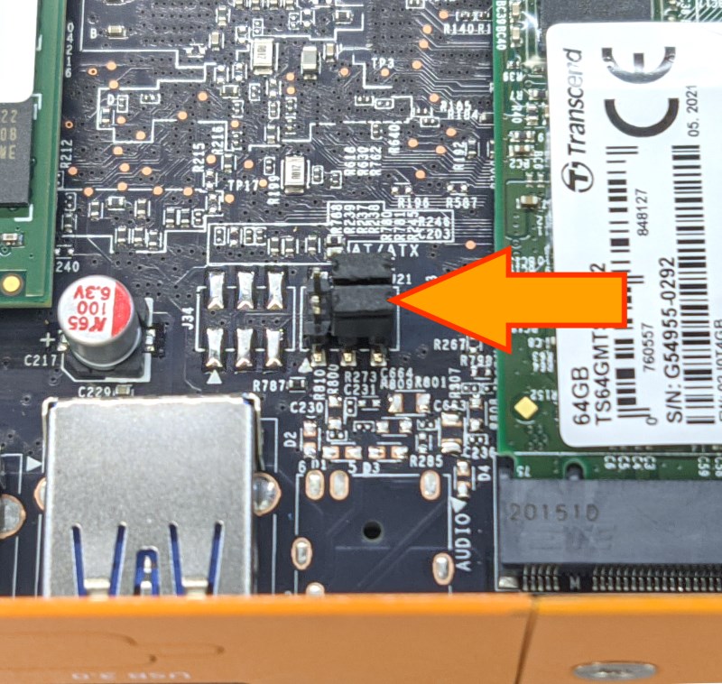
- The bottom jumper in this image (closest to the outside of the system) controls auto power on. It is called the AT/ATX jumper.
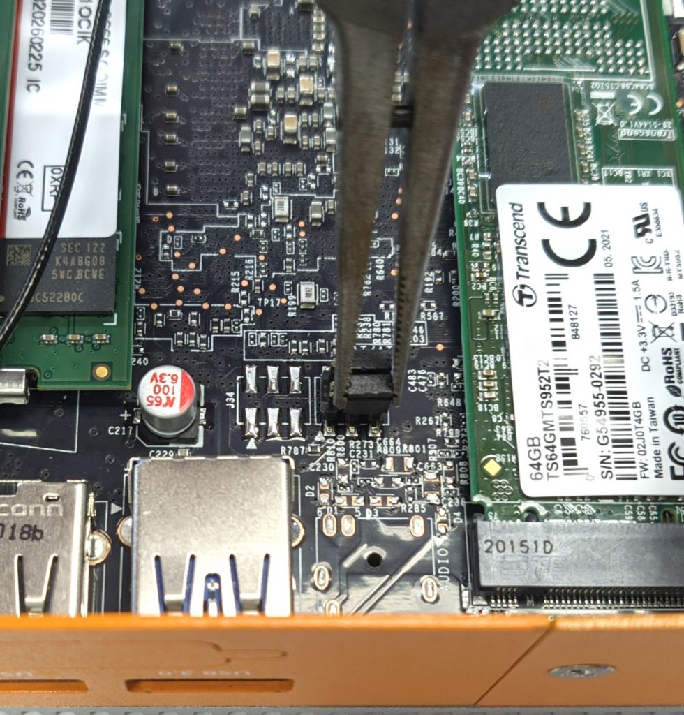
- Use needlenose pliers or your fingernails to grab the jumper and remove it from the pins.
- Reinstall the jumper as shown.
- Auto power on is now enabled (AT Mode)
Troubleshooting
Clearing the CMOS
If your unit fails to boot or power on, a CMOS reset may help. You will need to open the unit to perform the reset. This does not void your warranty, however, any damage caused by doing so will not be covered. Ensure your body is discharged of any static electricity by touching a grounded metal surface.
- Follow the Disassembly Guide directly above
- Locate the jumper shown here in purple
- The top jumper shown here will clear the CMOS.
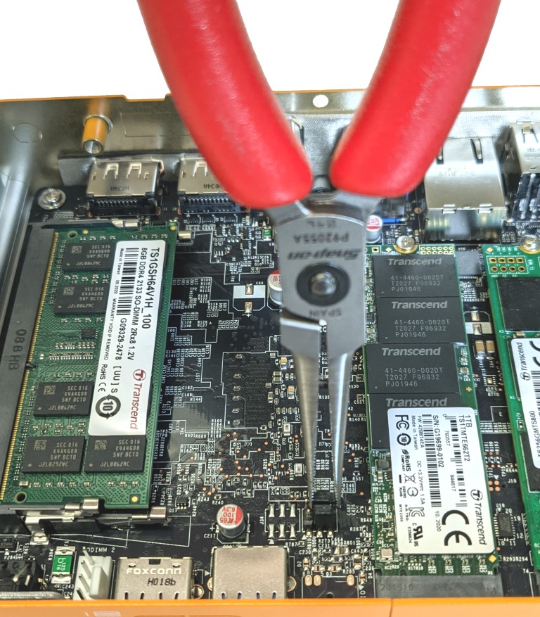
- Use needlenose pliers or your fingernails to grab the jumper and remove it from the pins.
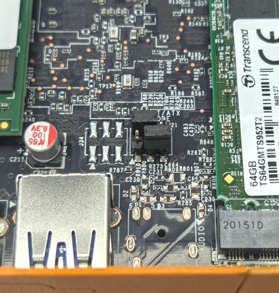
- Reinstall the jumper as shown.
- Leave the jumper in place for 30 seconds.
- Restore the jumper to its original position
Replacing the CMOS battery
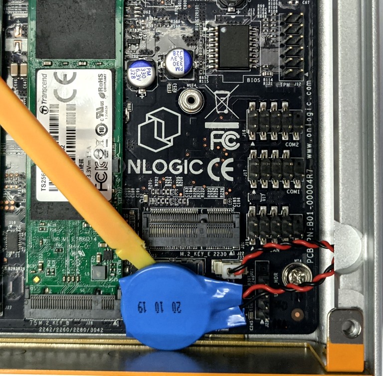
- Follow the Disassembly Guide directly above
- The CMOS battery is held in by a light adhesive. Pull the battery off the board and take care not to damage any components on the board.
- Pull the wire straight up to unplug the battery from the board.
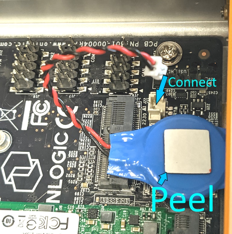
- Plug the new battery into the board
- Peel off the adhesive and stick it in place so it does not rattle around.
- The BIOS settings and time will be reset when the unit is powered back on the next time.
Ubuntu boots up slowly / doesn’t turn off completely
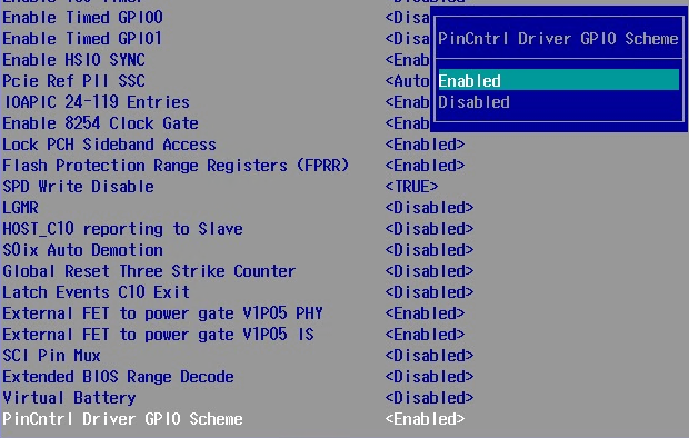
If you are having issues with Ubuntu randomly crashing, taking several minutes to boot up, or an issue with not fully turning off, try Enabling the PinCntrl Driver GPIO Scheme:
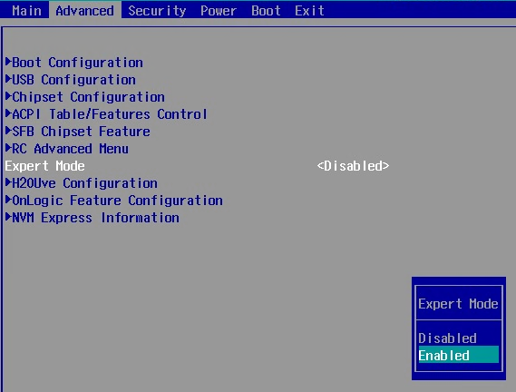
- Access the BIOS by pressing DEL while the system is booting up
- Enable Expert Mode under Advanced
- Enable Pin Control Driver GPIO Scheme:
Advanced/
RC AdvancedMenu/
PCH-IO Configuration/
PinCntrl Driver GPIO Scheme -> Enable - Press F10 to
Save & Exit
System won’t PXE boot
To support PXE (network boot), update your system to the latest BIOS revision available at this support page (linked above). Note that any operating system booted over PXE will also need Ethernet drivers in order to function. Windows drivers are also available at the top of this page.
Using the TPM 2.0 Module
As with other newer model systems, this model includes a firmware TPM by default. It functions similarly to a TPM 2.0 module. If the optional dedicated TPM 2.0 module is added to the system, the firmware TPM will need to be disabled to allow it to function.
The firmware TPM can be disabled in the BIOS:
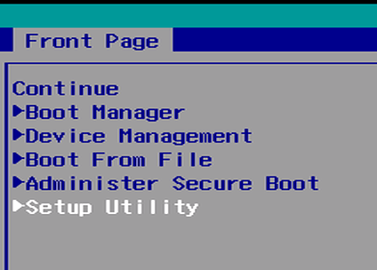
- Power on the system and press the Del key to access the Front Page menu.
- Choose the Setup Utility option.
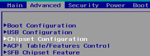
- Under the advanced tab, open the chipset configuration menu.
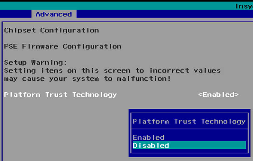
- Disable Platform Trust Technology
- Press F10 to save and exit.
- The dedicated TPM will now be functional. You can verify it is detected in TPM.MSC or Device Manager.
Digital IO and CAN
The Helix 300 and 310 systems offer optional CAN bus and isolated Digital IO support. This functionality is through the processor’s supporting ARM microcontroller, known as the Programmable Services Engine (PSE).
The PSE is isolated from the core processor, runs its own OS (Zephyr RTOS), but can be sent messages over the system’s Host Embedded Controller Interface (or HECI). The OS is transparent to the user. This interface may be used to send and receive CAN messages alongside setting and reading the Digital IO.
Quickstart
Requirements: An HX300 or HX310 with Windows and the latest HECI driver. The HECI Windows driver is provided and supported by Intel, and will be preinstalled on HX300 units purchased with Windows. If Windows is installed by the user, the driver is included with our driver package linked at the top of this page.
- Download the HX300’s hardware control command line application.
- Open a command window, and navigate to the location of the downloaded file.
- Press the Windows Key + R
- Type
cmd.exeand hitEnter - In the window that opens navigate to the download location:
- e.g.
cd C:\User\Username\Downloads
- e.g.
- Display the built-in help text:
hwc.exe --help
DIO Examples
The (optional) MOD110 digital input/output (DIO) expansion adds up to eight digital inputs and outputs to the system, and an additional CAN port. It also optionally provides support for pulse width modulation (PWM) on three of the eight digital output pins, and support for using a quadrature encoder peripheral (QEP) in place of the first and/or second group of three digital inputs.
See our dedicated DIO article on how to get started with the expansion module, the MOD110.
Application Integration
The HECI interface uses packed structures to send data between the host and PSE. Specific type structures are provided in the sample code, but an outline of the message format is available below:
| Bits | Description |
| 0 – 7 | HECI Command Identifier: 0x01: System Information: 0x02: Digital IO 0x04: Can Bus |
| 8 | Set as ‘1’ if this message is a response from the PSE |
| 9 | Set as ‘1’ if this message contains a valid data body |
| 10 – 25 | Packed ‘argument’ for a given command. Format depends on the command identifier. |
| 26 – 31 | Status of last command |
| 32 – 39 | Data format of body: 0: Raw data 1: Version information 2: CAN message 4: DIO message 7: ASCII String |
| 40 – 168 | Body of message data, usually in the form of another packed structure. |